Blog: Bullets from the Clouds – The first principle view for Industrial Automation
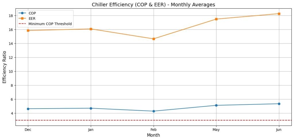
Recently, we were engaging with a client for automating their existing production line. This essay is built on some of the discussion we had with their team, which consisted of shop floor engineers, consultants, people from finance and higher management. Though the client aggressively wanted to pursue automation, as consultant, it was important to drive the conversation so that all stakeholders were on the same page i.e. the management should have similar appreciation of the challenges which may be obvious to the process or instrumentation engineers. While the client discussion happened over several meetings, the overall perspective on how we approach process automation guided by ‘first principles’, makes an interesting topic worth elaborating. The bullets in my title are not the bullet points of some presentation on best practices of using cloud infrastructure for automation. The bullets I refer to are the fast-moving projectiles and the clouds are the clouds that you see when you look up to the sky. If you want to develop ability for ‘first principle thinking’, you will have to keep revisiting basic mathematics and laws of physics. Coming back to the cloud, lets revisit 9th grade physics and mathematics. The laws of motion: v = u + at s = ut + ½ a t2 , so v = (2as) 1/2 If a cloud is at a height of 10,000m a simple calculation, using acceleration due to gravity as 9.8m/s2 and starting velocity (u) as 0, shows that the speed of the rain drop by the time it reaches ground level would be 447m/s or 1610kmph or 1.34 Mach (1.34 times the speed of sound). At 447m/s the rain drop would be at the speed of a typical bullet fired from a handgun. And that’s when it starts at 10,000m. There are clouds even higher. Essentially life on earth as we know it, both plant and animal would not exit if rain drops hit the surface at that speed. However, raindrops fall at under 10m/s, mostly at 2-5m/s. Well, as we all know, that’s because of ‘drag’ or friction in the opposite direction from the air. In fact, the drag force is proportional to the square of the velocity i.e. they increase rapidly as the velocity increases and at one point the force from gravity is balanced by the drag force and the falling object stops acceleration i.e. it reaches what is called Terminal Velocity. Acceleration = g – α v2, where α is some factor. The graph below is constructed by a XLS simulation. Give the values of acceleration due to gravity and the drag force, regardless of the initial velocity, 0 or say 300, the object will tend towards a stable velocity. First Principle Thinking So, what exactly is the First Principle Thinking here and how does it apply to Industrial Automation. The most basic mechanism to understand here in ‘the closed loop feedback’, especially the ‘negative feedback’ of the closed loop. Any stable system would have a negative feedback loop. This is a very general principle that we can see in various places around us, both naturally occurring as well as in systems designed by humans. There are potentially limitless examples of a self-regulating closed negative feedback loop in nature. As engineers, we design systems in similar ways. The most basic examples being: There are other examples in society too, like Awareness of these fundamental principles can help us define the situation in a more precise manner which in-turn helps to communicate to a diverse set of stakeholders a singular view of what the group needs to achieve. The wider perspective also opens the possibility of innovation by ‘transfer learning’ i.e. ability to apply general principles from one domain to another. Future innovations are increasingly going to come from those who are able to see and relate across multiple domains. Industrial Automation I have already listed some engineering scenarios that are fundamentally a ‘closed loop negative feedback system’ and when precisely engineered, bring stability and predictability to industrial system. A client in Chemical Process industry wants to automate their entire production. The vision was to move towards a ‘Dark Factory’ i.e. totally automated and with no need for any human intervention, you don’t need any light in the factory. Our discussions with the production engineers ultimately lead to the question ‘How to stabilize’ a process? To stabilize without constant human monitoring. By now the answer is obvious – we need to implement a ‘closed loop negative feedback system’ across the plant. The basic problem, however, was that the output cannot be tested real-time. The production was a continuous process and from time to time a sample would be drawn and sent to the laboratory for testing. The lab testing itself took few hours for the results. Clearly a closed loop self-correcting system was not possible. How do we approach this problem? Since a closed loop system was not possible, let’s look at typical ‘Open Loop’ system. 2. Unstable System: Unstable open loop processes are those whose output values are not bound by input and therefore may run away on either side. Typical example would be exothermic reaction leading to an explosion or even a nuclear chain reaction. AI/ML and the Pseudo Closed Loop. The way to automate such processes is through establishing empirical, data driven relationship. Enter Regression Analysis Time series data was collected on various parameters and a regression analysis (OLS – Ordinary Least Square) was done. The R-squared values helped identify which of the independent variables had the most impact on the dependent variable, which in this case was one specific parameter(Y) of the end product. Y = β0 + β1X1 + β2X2 + β3X3+……. + βpXp + ε Putting together the two concepts together By stabilizing the input (say temperate by using a thermostat) we can try to keep the output within a narrow limit. Using Sisai’s Ficus range of edge devices and the CrowSensor platform we can implement a pseudo closed loop process control system that would